| Case Name |
Fracture of Turbine Shaft in Wakayama |
| Pictograph |
|
| Date |
June 5, 1972 |
| Place |
Wakayama, Japan |
| Location |
Kainan Thermal Power Station of the Kansai Electric Power Company |
| Overview |
Turbine and generator shafts fractured during a test run of 600,000-kilowatt steam generator unit conducted at a thermal power station. Fragments of the turbine, the generator and the exciter scattered in the area. The generator caught a fire. Inadequately adjusted bearings caused turbine-blade vibrations, and resonance. |
| Incident |
Turbine and generator shafts fractured during a test run of 600,000-kilowatt steam generator unit conducted at the Kainan Thermal Power Station of the Kansai Electric Power Company. Fragments of the turbine, the generator and the exciter scattered in the area. The generator caught a fire. |
| Sequence |
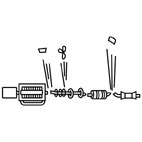
The steam generator unit had a coupling mechanism as shown in Figure 1, in which 9 couplings and 11 bearings secure connections between the shaft of the generator and the shaft of a rotating object such as an axle or wheel.
After engineers adjusted the bearing balance at the factory, the equipment was shipped in April to the power station to have them assembled and the coupling mechanism affixed to the generator. While engineers had adjusted the bearing balance 62 times by June 5 when the incident occurred; the engine had been experiencing intense turbine-blade vibrations at bearing #11 since May 27. After completing the balance adjustment and the test run at the normal operation speed of 3,600 rpm, engineers increased the turbine speed to the maximum, 3,850 - 3,900 rpm to check the turbine-blade vibrations. As engineers started decreasing the turbine speed from 3,850 rpm, the engine made a loud rasping noise. Within several seconds after the generator vibration alarm activated the trip (emergency shutdown), the end shaft of the generator (#10) caught a fire. Engineers turned off the boiler to decrease the pressure when the turbine, the generator and the exciter fractured with heavy banging noises. Fragments scattered in the area, and the fire broke out from the generator. Figure 2 and 3 show the damaged turbine generator and rotor. One of the fragments flew 380 meters, the longest distance of all, as Figure 4 illustrates. |
| Cause |
The housing of bearing #11 failed to secure the bearing stand and the upper vibration-absorbing pad. The vibration occurred during the bearing adjustment loosened the upper vibration-absorbing pad (the upper half of the journal bearing seat), and the loosened pad fell off (Figure 5a). This decreased the critical whirling speed (resonant frequency) of the shafting, which influenced the bearing vibrations and resulted in structural resonance. The structural resonance caused abnormal vibrations, which led to loose or deformed bearings, housing and bolts (Figure 5b). Violent vibrations at bearings damaged the refueling system. Bearing metal partially melted down because of the interrupted refueling. Violent vibrations also scraped off or deformed the bearing metal. Damaged bearings failed to secure the shaft, which led to the destruction of the rotating shaft due to abnormal axial displacement between the shaft and the housing (Figure 5c).
The damaged generator bearing and seal allowed hydrogen gas to leak out of the generator. The leaked hydrogen gas was ignited, causing a fire (Figure 5d). Most power generating plants use hydrogen gas to cool the electrical windings within the power generator. This improves operating efficiencies by lowering the losses due to the resistance of the windings (windage loss). |
| Response |
All devices were rebuilt at the factory. Engineers installed the bearing and performed vibration diagnostics. |
| Countermeasures |
Instead of adjusting the bearing for each device and readjust bearings of the assembled turbine generator, the bearings were adjusted as connecting devices so that the assembled turbine generator do not require bearing readjustment. |
| Knowledge Comment |
(1) A high-speed rotating shafting produces a whirling motion.
(2) When whirling magnifies from resonance, the rotating body with centrifugal force can burst out and cause serious accidents.
(3) Every failure comes with an infallible indication of some sort. It is critical not to miss it and to take an appropriate action before an indication lead to a failure.
(4) Never stand near on the plane of rotation when one must be near a rotating machinery. Early propeller aircrafts did not have see-through covers over the propeller blades' plane of rotation. |
| Background |
A steam turbine is a rotary engine that extracts energy from a steam flow. It is the main mechanical device of a power generation system that extracts thermal energy from pressurized steam by sending steam in high pressure and temperature to the blades attached to a shaft (the rotor assembly). The blades react to the flow so that they rotate and impart energy to the rotor. The generator connected to the turbine convert the energy into electricity, which is supplied to communities. Leading domestic manufacturers at time had technical collaboration with foreign manufacturers such as Westinghouse (U.S.), General Electric (U.S.) and Siemens (Europe) to develop turbines. Domestic development of turbine technology was yet to come. The industry did not have fully developed balance adjustment technology for multi-bearing rotor systems. Turbines were shipped back to the factory to adjust bearings, if engineers were unable to adjust them after assembling the turbine. |
| Scenario |
| Primary Scenario
|
Unknown Cause, Occurrence of Abnormal Phenomenon, Usage, Operation/Use, Regular Movement, Careless Movement, Failure, Large-Scale Damage
|
|
| Sources |
[1] Yotaro Hatamura (Editor), Jissai-no Sekkei (Practical Design) Research Foundation (1996) Zoku-Zoku Jissai-no Sekkei (Practical Design III), The Nikkan Kogyo Shimbun, LTD.
|
| Multimedia Files |
Figure1.Schematic Diagram of 600,000-Kilowatt Unit [1]
|
|
Figure 2.Damaged Turbine Generator Shaft [1]
|
|
Figure3.Damaged Rotor Shaft [1]
|
|
Figure4.Scattered Fragments and Flying Distances [1]
|
|
Figure5.Turbine Failure: Sequence of Events
|
| Field |
Mechanical Engineering
|
| Author |
NAKAO, Masayuki (Institute of Engineering Innovation, School of Engineering, The University of Tokyo)
|