| Case Name |
Bursting of a scuba cylinder made of an aluminum alloy |
| Pictograph |
|
| Date |
June 30, 2000 |
| Place |
Miyako-jima, Okinawa Prefecture |
| Machinery |
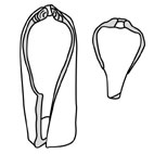
A scuba cylinder made of an aluminum alloy (Capacity: 10.3 liter, External diameter: 185mm, Thickness: 13.5 mm, Length: 628 mm, Material: A6351-T6, Maximum filling pressure: 21.6 MPa (220kgf/cm2), Manufacturer: Luxfer Gax Cylinders. (See Fig_1) |
| Overview |
Scuba or aqualung is an automatic self-breathing system for underwater diving, and it has been widely used for leisure diving. A scuba cylinder made of an aluminum alloy suddenly burst right after it was filled with air. According to the investigation after the incident, it was identified that there were a number of the cracks along the axis of the screw part of cylinder. The causes of the cracks were inter-granular corrosion and stress corrosion cracking (SCC). Countermeasures, such as the revision of the regulations for the safety of scuba cylinders, were carried out. |
| Incident |
*********************** Refer to 100 Selected Cases. ************************** |
| Sequence |
On August 23rd and September 8th, 2000 and April 24th, 2001 an advisory bulletin was issued to each prefecture for distribution to the owners of scuba cylinders, air filling stations and cylinder inspecting stations by the Safety Division of the Nuclear and Industrial Safety Agency (NISA) of the Agency for Natural Resources and Energy (ANRE) in the Ministry of Energy, Trade and Industry (METI).
After the cracking was found in the cylinders made of A6061-T6, the NISA informed each prefecture on July 4th, 2001 that a committee had been established by the NISA in the High Pressure Gas Safety Institute of Japan (HPGSI) to investigate the possibility of bursting of cylinders made of A6061-T6.
The committee for the investigation of the scuba cylinders made of aluminum alloys, chaired by Professor Hideo Kobayashi of the Tokyo Institute of Technology, completed its investigation and opened its report to the public on the HPGSI website on October 19th, 2001. |
| Cause |
This case had a typical complex set of causes. Six causes are shown below. If one of these causes had not occurred, the burst accident would not have happened.
(1) Material (A6351-T6)
In proper selection of a material which is susceptible to continuous load cracking, inter-granular corrosion, and stress corrosion cracking
(2) Manufacturing (coarse crystal grain)
Inadequate procedure for manufacturing and heat treatment of the head part of the cylinder
(3) The occurrence of interstitial water and salt in the cylinder
(4) The extreme difficulty of observing the cracking during visual inspection
(5) No occurrence of LBB (Leak Before Burst)
It is required that there should be LBB at the maximum filling pressure during the manufacturing. That is, even if the cracking on the surface caused and extended by the stress corrosion cracking, a detectable leakage should precede the burst by the penetration of cracking, so the safety can be maintained. However, LBB is only required for the parts of the container that are thinnest. The screw, shoulder and bottom of the container, which are thicker than body, are not subjects of the requirement. It was found that the LBB was not enforced for the thumb-nail cracking at the screw part.
(6) The lack of other accident information
There were similar accidents in foreign countries, but the information regarding those accidents was not properly conveyed. |
| Response |
The material used for scuba cylinders has been changed from A6351-T6 to A6061-T6. However, cylinders that are made of A6351-T6 are still being widely used. Furthermore, cracking along the axis in the screw part of cylinders that are made of A6061-T6 was also found. Therefore the following practical countermeasures are suggested.
(1) Apart from the inspection conducted once every five years, the owner of the scuba cylinder should be required to conduct a visual inspection for finding cracking along the axis in the screw part. This inspection should be required by law. It should be noted that special technique and experience are required for proper visual inspection.
(2) Air filling operators should be warned of the importance of the competence and maintenance of the air filling station.
(3) Owners of scuba cylinders should be warned of the importance of protecting cylinders from interstitial water and salt.
(4) Manufacturers and importers should be required to improve the criteria for the manufacturing and heat treatment of the head part of the cylinder. The rental system for scuba cylinders is widely used. Therefore, the user of the scuba cylinder is not always the owner. The relationship, processing chain and responsibilities of the user, the owner, the operator of the air filling, the inspection station, the manufacture, and the importer must be clarified.
(5) Research on stress corrosion cracking of the 6000 series aluminum alloy should be increased. |
| Countermeasures |
Based on the results of the study by the committee for the investigation of scuba cylinders made of aluminum alloys, on October 19th and November 23rd, 2001, a meeting of the high pressure gas division of the high pressure and gunpowder safety branch of the Research Committee for the Natural Resources and Energy was held. In the meeting, an article on "the concrete method of the countermeasures for the maintaining safety of scuba cylinders made of aluminum alloys" was recommended for inclusion in the report.
Special proposal was made for the revision of the safety regulations for cylinders to require a visual inspection of the screw part once a year in addition to the full inspection conducted once every five years.
Thus, according to this proposal, the additional clause (the ministerial ordinance No. 84 issued on June 10th, 2002) of the safety regulations for cylinders (the ministerial ordinance No. 50) was put into effect. This clause specifically establishes that the period of inspection of scuba seamless cylinders made of aluminum alloys be once a year in article 24 of the safety regulations fr cylinders. It was also establishes that the inspector must certify that there is neither harmful damage such as the cracking along the axis of cylinder nor malfunction around the screw part in article 3 No. 5 of notice No. 150 (visual inspection), which establishes the various details such as markings as well as the inspection methods based on the safety regulations.
The High Pressure Gas Safety Agency had voluntary standards, "the regulations for an inspection of the cylinder for the scuba (KHKS 004-1983)", that were actually applied. However, the standards were old and intended for cylinders made of steel. Therefore, taking into account the proposals from the investigation of the accident, a revision of the standards was commenced with the intention of treating both aluminum and steel cylinders.
The committee for the revision of the regulations for the inspection of cylinders for SCUBA, which was chaired by Professor Hideo Kobayashi, Tokyo Institute of Technology and established in the cylinder division of the technical members of the High Pressure Gas Safety Agency, held its first meeting on January 24th, 2002. The self-established regulations, "regulations for the inspection of seamless cylinders for scuba", were published in July 2002. |
| Knowledge Comment |
Complex causes:
The most accidents are caused by the results of conflicts among a number of individual causes. In accidents having complex causes, the projecting cause will usually be regarded as the major cause. There are two causes of complex causes. In the first case, there is one major cause, and the other causes just accelerate the major cause. In the second case, there are a number of major causes, and if any one of the major causes fails to occur, the accident will not happen.
Particularly in the investigation and analysis of accidents involving the destruction of machinery, the material is generally named as the major cause, and investigations and experiments are focused on the material. That is, the material is treated as being suspect from the beginning. This is natural, because the destruction of the machinery is the destruction of material. The problem is with the conclusion of the investigation and analysis of the accident. In Japan, the number of major causes given for an accident is usually very large, and therefore the material related factors will certainly be named among the major causes. The designation of a large number of causes is based on an aspect of Japanese culture that stipulates that the social responsibility of an accident should be vague and the responsibility should be divided between 1) the user and manufacturer of the machinery, and 2) the manufacturer of the material.
It is necessary to study sufficiently the results from a complex cause and to carefully consider the results. |
| Incidental Discussion |
The English name for a pressure vessel is 'cylinder". However, in Japanese, a pressure vessel is called "bomb". A bomb in English is an explosive, and a Japanese 'bomb' carries this meaning as something that could explode, becoming a deadly weapon that flies around after the explosion.
* Applications of the vessel
The applications of the vessel range from industrial use, to medical use, home use and leisure. The gas contents vary with application, such as air, oxygen or nitrogen.
* Shape of the vessel
The shape of the vessel is similar to that of a sake bottle in that it has a thin neck, a broad bottom and a raised bottom. The function of the thin neck is to serve the contents a little at a time. The function of the broad bottom is for stability when standing upright. The function of the raised bottom is for increasing the stability in the upright position.
* The material of the vessel
The gas is light but the vessel is heavy. In the past, the vessels were constructed to be stout and heavy like a safe because the gas was considered to be precious and dangerous. However, mass consumption of the gases has changed this perspective, and in accordance to the request for lower weight, the material has been changed from steel to aluminum and further to composite materials.
* Corrosion starts from the bottom of a vessel
When the vessel made of steel is exposed to rain, it starts to corrode from the outer surface and bottom. Cases where a hole penetrates the body and the vessel explodes occur more often when corrosion starts from the outer surface than when corrosion starts from the inner surface.
* How much corrosion can the vessel incur and still be safe ?
A vessel will be safe even if half of the body thickness is corrode. Vessels are built to be that strong.
* The vessel itself is a projectile
When a vessel explodes, in addition to splinters of the vessel material, the vessel itself can become a projectile. If the valve is opened abruptly, the vessel would fly like a rocket because of the pressure release. A light vessel will fly more easily.
* The gas must leak before the explosion
It is dangerous if a vessel explodes suddenly. Even if stress corrosion cracking occurs, if the gas leaks before the explosion when the cracking penetrates the body, the potential for explosion would be detected, and it might be possible to avoid the explosion by lessening the pressure. This is called Leak Before Break/Burst, or LBB. According to the manufacturing standards for vessels, design for LBB is required. With LBB design, we can be confident that the gas will leak before the explosion. |
| Scenario |
| Primary Scenario
|
Ignorance, Insufficient Knowledge, Prejudice, Production, Hardware Production, Manufacturing of machinery and equipment, Cylinder, Aluminum alloy, Inappropriateness of material decision, Inappropriateness of manufacturing and thermal treatment condition, Usage, Operation/Use, Use of equipment and material, Interstitial water and salt, Failure, Fracture/Damage, Stress Corrosion Cracking (SCC), Usage, Maintenance/Repair, Inspection, Difficulty of crack detection, Failure of Leak Before Break (LBB), Failure, Large-Scale Damage, Burst
|
|
| Number of Deaths |
0 |
| Number of Injuries |
1 |
| Multimedia Files |
Fig_2.Major dimension of cylinder
|
|
Fig_3.Fracture surface of broken cylinder
|
|
Fig_4.Old fracture surface
|
|
Fig_5.Thumbnail-shape fracture surface
|
|
Fig_6.Metallographic observation results
|
|
Fig_7.Fault tree diagram for mode, mechanism and process of fracture
|
|
Fig_8.Fault tree diagram for design and manufacturing errors (1)
|
|
Fig_9.Fault tree diagram for design and manufacturing errors (2)
|
|
Fig_10.Fault tree diagram for loading history, environment and material
|
|
Fig_11.Fault tree diagram for cylinder reexamination
|
|
Fig_12.Event tree diagram for cylinder burst due to SCC
|
| Field |
Material Science
|
| Author |
KOBAYASHI, Hideo (Yokohama National University)
|
|