| Case Name |
Failed launching H-2 Rocket 8 |
| Pictograph |

|
| Date |
November 15, 1999 |
| Place |
Kagoshima prefecture(Tanegashima Island) |
| Location |
Tanegashima Space Center of NASDA |
| Machinery |
H-2 Rocket 8, LE-7 Engine, Liquid hydrogen turbo pump, inducer blade |
| Overview |
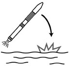
Approximately 4 minutes after its launch, the first stage engine(LE-7) suddenly stopping its combustion earlier than planned. The rocket turned uncontrollable and fell.
The LE-7 engine was recovered in January from the bottom of the sea, about 3,000m deep, outside of Ogasawara islands. The Ministry of Education, Culture, Sports, Science and Technology(MEXT), Spece Development Committee, Technology Evaluation Group conducted a study and identified the cause of the accident. |
| Incident |
The following paragraphs show the results from Fault Tree Analysis.
Fig.2:Fault tree diagram for mode, mechanism and process of fracture.
One of the three inducer blades, made of titanium alloy, had a large break at its root. Analyzing the fracture surface concluded that the fatigue crack originated from cutting mark of 15 micrometer depth and grew with semi-elliptically shape due to repeated stress to cause the fast fracture. The inducer blades are subject to mean stress (580-630MPa), a combination of membrane stress from centrifugal force and bending stress. The fracture surface analysis indicated the final fast fracture stress of 904MPa.The stress range estimation assuming stress repetition from bending was,therefore, 550-650MPa. This range roughly matches the striation spacing analysis results. Assuming a stress range of 650MPa results in the fatigue crack initiation life of Ni=5.5x10⁴-1.1x10⁵, and the fatigue crack growth life of Np=2.2x10⁴.
The fracture surface indicates one large stress range repetition (647MPa) for every 10 cycles of a smaller stress range (517MPa) repetition. The blade has a natural frequency of about 3,200Hz. Assuming the small stress range frequency at this value, the fatigue crack initiation life for the large stress range comes out 171 to 342 seconds. The fatigue crack growth life for small stress range is 6.9seconds. Summing the two yields 178 to 349 seconds and the 4 minutes which took the engine to stop after the launch falls into this range.
Fig.3:Fault tree diagram for design and manufacturing errors. The fatigue fracture originated from a 15micrometer deep cut mark. This is within the design standards range.
Fig.4:Fault tree diagram for loading history, environment and material.
The following are the results from the event tree analysis.
Fig.5:Event tree diagram for the inducer blade fatigue fracture caused by vibration.
The following two are possible sources of vibration to cause stress repetition responsible for the fatigue fracture.
(1) Vibration stress due to swirling cavitation caused by the pressure reduction control of the liquid hydrogene tank (270MPa).
(2) Vibration stress due to the blade resonance cause by changes of the inlet pressure (130MPa).
The stress ranges from (1) and (2) above are each less than the estimated range of 550-650MPa from the fracture surface analysis. Even their sum of 400MPa does not exceed the estimate. |
| Sequence |
The LE-7 engine was retrieved from the ocean bed about 3,000m deep near Ogasawara islands. The Ministry of Education, Culture, Sports, Science and Technology, Space Development Committee, Technology Evaluation Group conducted a study to clarify the cause of the accident. |
| Cause |
Unexpected vibration caused fatigue fracture in one of the inducer blades, which then triggered failure of the liquid hydrogen turbo pump which abruptly stopped.
The study did not identify the vibration source nor quntify the vibration stress. |
| Response |
(1) Reducing abnormal vibration
The modified LE-7A engine prevents swirling cavitation and at the same time, allows data collection of pressure variation over a wide range that includes actual operation state during an engine combustion test, and of pressure variation and vibration data during an inducer water flow test.
(2) Fatigue analysis
The fatigue due to vibration was an unexpected event for the inducer blade design. The inducer, as well as other important parts, should go through fatigue analysis and data acquisition of the material fatigue characteristics (e.g., S-N curve, crack growth characteristics) under cryogenic environment.
(3) Cut mark
The 15micrometer deep cut mark which intiated the inducer blade fatigue fracture was within the design standards range. It is needed to reevaluate the design standards for improving machining precision and cut marks including specifying new inspection methods. |
| Countermeasures |
The LE-7A engine mounted on the H-2A rocket (launched Feb.4th,2002) had implemented the countermeasures based on the actions. |
| Knowledge Comment |
"Unexpected Event"
The design process assumes possible events and plans measures for these expected events. Most expected events and actual measures are specified in the design standards (design by rule). The design standards, however, are not perfect and totally new designs, design by analysis with high degrees of freedom, deverted designs often experience unexpected events that may lead to accidents. Designers are required to assume events that directly lead to accidents. |
| Scenario |
| Primary Scenario
|
Ignorance, Insufficient Knowledge, Planning and Design, Poor Planning, Bad Event, Thermo-Fluid Event, Production, Hardware Production, Failure, Fracture/Damage, Malfunction, Poor Hardware, Failure, Large-Scale Damage
|
|
| Sources |
(1) Report: Identifying the cause of failure for the H-2 rocket 8 launch. MEXT Spece Development Committee, Technology Evaluation Group, May 18,2000
|
| Number of Deaths |
0 |
| Number of Injuries |
0 |
| Multimedia Files |
Fig1.Retrieving the engine from the ocean
|
|
Fig2.Fault tree diagram for mode, mechanism and process of fracture
|
|
Fig3.Fault tree diagram for design and manufacturing errors
|
|
Fig4.Fault tree diagram for loading history, environment and material
|
|
Fig5.Event tree diagram for the inducer blade fatigue fracture caused by vibration
|
| Field |
Material Science
|
| Author |
KOBAYASHI, Hideo (Yokohama National University)
|
|